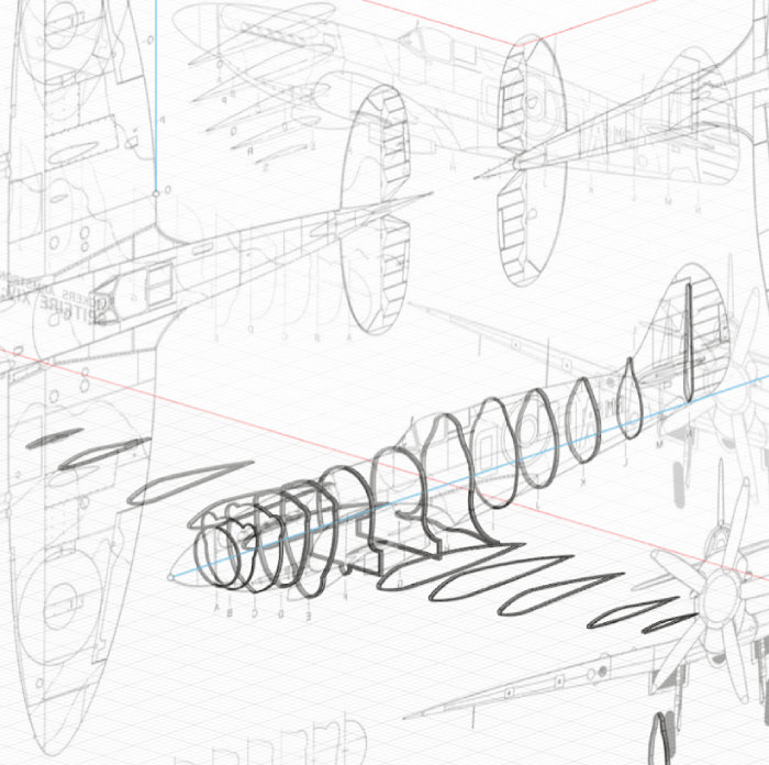
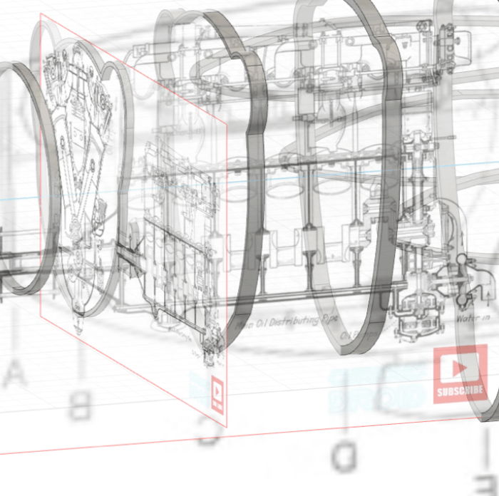
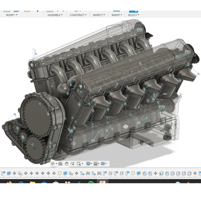
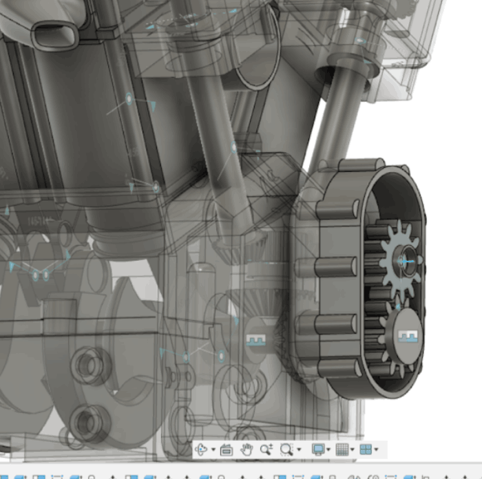
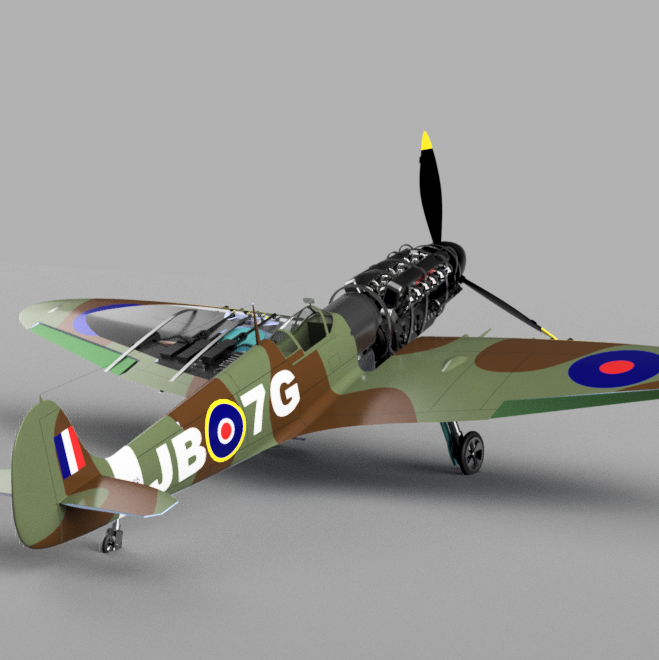
The brief asked the team for a website with a 3D model of the Spitfire which could take a user through the components and the people’s stories behind them. Therefore, I was tasked with the internals and build of the component features of the Spitfire. I began with researching the Spitfire for a few weeks and building a mental idea of how I was going to build the assembly. As always, I started with importing the orthographic blueprints.
These blueprints very handily came with plans of the cross section of the fuselage and the wing shape. I used these cross sections to make the guide rails that line the inside of the fuselage. These could then be positioned in the correct places to give me a general shape for the aircraft.
Following getting an idea for the general shape of the aircraft I could bring in orthographic projections of the engine assembly and position these canvases in the correct place. This then served as a template for positioning my components once I had created them.
For the main engine block, I began by making a single piston engine and crankshaft then used Fusion 360s assembly feature to join these and make them behave in the reciprocating to rotary motion that occurs. Following making one I could copy this assembly multiple times and offset the crankshaft by a third turn each time so that the engine was positioned and balanced correctly. Then I could add all the hard surface components shown here on the right.
For the four overhead valves in the Merlin engine I used hard surface modelling to create one, then made the complex spring helix and wrapped it around. I then used a circular pattern arrangement to position the four of them in a rectangular fashion. Then I could use a motion study and program in the incremental displacement to time the valves to go down once every two full revolutions of the crankshaft.
For the complex geometry of the pipework of the intake, I used soft sculpt modelling. This allowed me to get the basic shaped of the pipework correct before turning it into the circular smooth pipe used in the final product. I also used this method for all the pipes I created.
Visible here is the Cam shaft located on top of the pistons also visible is the gearing at the front of the engine which will eventually lead to the propeller. For the gears I used Fusions built in spur gear add on, This saved me lots of time as I didn’t have to draw out a spur gear, but also as they vary in diameter they become more complex to be in constant mesh. However, Fusions add on completes all the mathematics for me, radically reducing the total research and build time. The exhaust caps I made using sculpt features of fusion.
The connecting rods which transfer the rotary motion from the crank shaft up to the cam shaft were difficult as these required tapered gears. For these I had to trace the spur gear using only straight lines then loft them upwards to a guide surface so that the angle was correct.
The Spitfire is supercharged and therefore required an impeller. This means that it is driven by the crankshaft of the engine, rather than the exhaust gasses like a turbo. It's note worthy here that to keep the geometry of the whole piece down I didn’t add individual screws. Instead I used cylinders to replace them as the individual threads make computers run slowly therefore for the final website this would be problematic.
Following this I added the smaller details. For example, the Merlin engine had a Rolls Royce written on the side, so I have added this as it is iconic to the design. I have also added: the oil pump, a higher detail oil pan, the fuel tank and other small features that make the engine more recognisable.
Following adding the rest of the body I had to make a decision on how to display the full model in both a way that is attractive to the audience, and shows as much of the inner workings of the aircraft as possible. Therefore, I have chosen to display it in the manner shown on the left, as the plane is still clearly recognisable with its iconic elliptical wings but you can see the machine guns in the wings and the engine in the front.
Following the completion of the assembly I used Fusion for this final render. Upon the render finishing I was not completely happy with it and thought that It could look better. Therefore, I thought it was finally time to step out of my comfort zone and learn a new program. So I decided to learn two, both Blender (an open source free software that uses the cycles engine) and Twin motion (which uses the Unreal engine.)
To the right is the final blender animations for the Spitfire. I am proud of myself for making this as Blender is a difficult tool to learn, and I managed to produce these renders. Autodesk (a different software) charge for rendering animations like this, therefore I have saved myself money here. However, it does have draw backs as each of those clips took over 2 hours to render and the final product is still grainy. It is also much more difficult to make an environment. Therefore I left the environment as a blank plane.
Twin motion has basically served as the opposite to Blender. This meant I could add a lot more environment detail and make things move around more but at the cost of the quality of the render. The actual video looks fairly poor but this is to be expected as Unreal is a video game engine not an unbiased architectural one.
This is the final assembly animation. Unfortunately, here you can begin to see the computational issues showing, as the assembly is complex it is beginning to make my computer lag. However, all the key components are visible here and I am very proud of what I have achieved in this project. I am now able to hand the model on to the developer to use in the final website app.
Click below to view the final group outcome.
To ask about any projects or to query about services do not hesitate to get in touch.
Made with Love and Caffeine By Matt Nugent